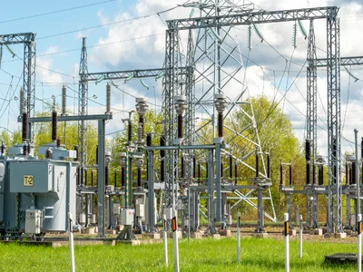
Based on engineering insights, the primary causes of busbar failures, exploring their technical principles, characteristics, and strategy for early detection.
Primary causes for Busbar failures are:
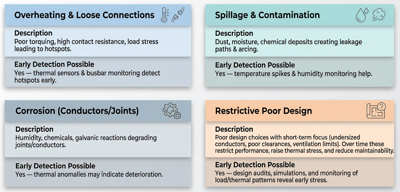
Overheating and Loose Connections
Among the most common issues in busbar systems is overheating due to loose connections. This condition often originates from improper installation methods, such as insufficient torquing during assembly. Torque typically ranges from 20 to 50 Nm depending up on bolt size and material to ensure optimal contact pressure between busbar joints. When torquing falls short, contact resistance alters which is governed by Ohm’s law, where resistance (R) inversely affects current flow and amplifies heat generation via Joule’s law (P = I²R).
High contact resistance, usually above 10-20 micro-ohms in faulty joints compared to less than 5 micro-ohms in healthy joints, creates localized hotspots.
Load stress further worsens the failures, as cyclic loading from fluctuating currents due to thermal expansion and contraction. Materials such as copper, expand at a rate of about 16.5 × 10⁻⁶ per °C, resulting mechanical fatigue and further loosening. In extreme conditions, temperatures may rise beyond 150°C, accelerating oxidation and even igniting insulation materials with flash points around 200-300°C.
Early detection can be achieved through thermal monitoring. Infrared thermography or embedded thermal sensors can identify temperature fluctuations, with anomalies like a 20-30°C rise above ambient signaling issues. Busbar monitoring systems track these in real-time, correlating data with load profiles to predict failures early.
Spillage and Contamination:
Another major risk is posed by environmental contaminants, which appear as spillage and surface contamination of busbars. Dust particles, moisture entry, or chemical residues from industrial processes accumulate and form conductive or semi-conductive layers. This creates leakage paths, reducing the dielectric strength of the air or insulation gaps.
Under clean conditions the air’s breakdown voltage is approximately 3 kV/mm, but contamination can drop this to under 1 kV/mm, making it easier for partial discharges or full arcing to occur.
Moisture, due to humidity levels of 60% RH or above, combines with dust to form electrolytic solutions, which causes tracking—a carbonized path that conducts current. Chemical residues, such as sulfur in petrochemical plants, react with metal surfaces, causing increase in surface resistivity and heat buildup. Arcing discharges ozone and nitric oxides which further degrades nearby components.
Monitoring humidity and temperature spikes is key for early intervention. Sensors detecting RH spikes or sudden temperature jumps (e.g., 10-15°C in minutes) can alert teams. Regular partial discharge testing using ultra-high frequency (UHF) methods helps monitoring contamination levels, allowing for timely cleaning or enclosure upgrades.
Corrosion in Conductors and Joints
Corrosion damages the integrity of busbar through electrochemical reactions, especially around conductors and joints. Humidity acts as catalyst in oxidation reactions, while chemicals like chlorides or acids causes pitting corrosion. Galvanic corrosion occurs due to presence of different metals such as aluminum busbars connected to copper fittings which creates a potential difference of about 0.25V, causing anodic dissolution. Over years, this thins conductors, increasing resistance and thermal stress.
Quantitively, corrosion rates can reach 0.1-0.5 mm/year in severe environments, affecting the current-carrying capacity. For a 1000A-rated busbar, a 10% cross-section loss might necessitate derating to 900A which can lead to potential overloads. Joints are hotspots, as corrosion products like oxides have resistivities orders of magnitude higher than that of base metals increasing the I²R losses.
Thermal fluctuations can be indicative of initial corrosion, as irregular heating can be sensed through sensors. Visual inspections combined with resistance measurements (using micro-ohmmeters) can estimate the degradation, while humidity can be controlled through dehumidifiers.
Restrictive Poor Design
Design flaws with a short-term perspective leads to restrictive configurations that impairs the effectiveness of busbar. Undersized conductors fail to handle peak loads, violating ampacity standards (IEC 61439 limits based on temperature rise). Poor clearances of less than 10-15 mm in medium-voltage applications increase the danger of flashover, while poor ventilation retains heat, thereby increasing ambient temperatures and aging.
These issues compound over time, undersized busbars have higher current densities (e.g., above 2 A/mm²), thereby increasing thermal stress according to Fourier’s law of heat conduction. Lack of maintainability due to congested layouts makes it difficult to inspect, allowing small problems to accumulate.
Early stress detection can be done from design audits and simulations using finite element analysis (FEA) to simulate thermal and electromagnetic fields. Monitoring load/thermal patterns via data loggers identifies irregularities.
Early Detection
In addressing these challenges, our solution “Busbar IQ” offers integrated advanced busbar monitoring. This system employs thermal sensors for real-time anomaly detection. Sends real-time alerts via SMS or email to prevent escalations. With compatibility across busbar types and fault diagnostics, it also features preventive strategies in a user-friendly dashboard, and thus minimizing the risks of downtime.
By prioritizing technical vigilance over these failure modes, electrical systems can minimizing the risks associated with downtime.