The progression follows a clear, predictable lifecycle. The asset managers and engineers need to understand these stages to intervene before any catastrophic failure occurs.
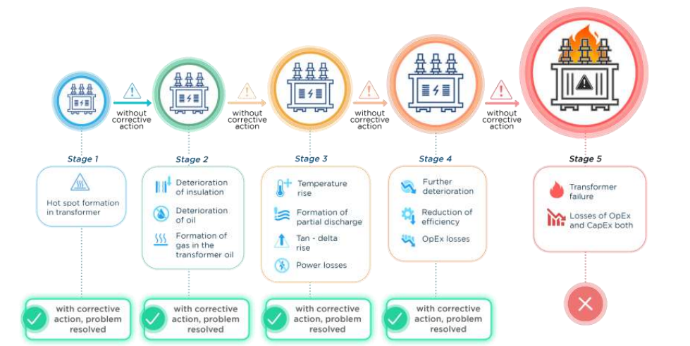
Stage 1: Hotspot Formation
Under sustained or cyclic overload, poor cooling, or uneven current distribution, a localized region in the winding, majorly toward the top, reaches temperatures significantly higher than the bulk oil or average winding temperature.
At this point, the hotspot may only be 10–20°C above permissible limits, but the damage mechanism has begun. Cellulose insulation starts indistinct depolymerization. The transformer appears healthy in routine checks as no gasses have become evident yet.
Stage 2: Insulation Deterioration and Gas Formation in Oil
As hotspot temperatures gradually rises, the paper insulation releases moisture and begins breaking down. Hydrocarbon gases, primarily hydrogen and methane start dissolving into the transformer oil. This is the first detectable sign in Dissolved Gas Analysis (DGA).
This issue can be resolved through early actions which include load management and improved cooling solutions without causing any loss of operational capacity.
Stage 3: Temperature Rise, Partial Discharge, and Rising Tan Delta
At this stage, the hotspot now drives broader thermal runaway. Partial discharges (PD) occurs in voids or degraded insulation, producing characteristic hydrogen and acetylene signatures in DGA. Tan delta (dissipation factor) rises as the dielectric loses integrity. I²R (Copper) losses and stray losses increase and causes noticeable power losses and efficiency drop.
Corrective action at this stage, such as oil reclamation, targeted repairs, or operational adjustments, can still avoid catastrophic failure.
Stage 4: Efficiency Erosion and Rising OpEx
Further use without any maintenance, deterioration accelerates. The transformer consumes more energy to deliver the same power output. Operating expenses increase due to increased losses, more frequent cooling fan/pump operation, and more frequent maintenance. The Insulation strength continues to degrade, bringing the unit close to critical thresholds.
Stage 5: Catastrophic Failure
When the hotspot exceeds thermal withstand limits, insulation failure causes inter-turn or inter-winding faults. This results in explosive failure, total loss of the asset impacting Capital Expenditure (CapEx), prolonged downtime, and safety risks. At this stage, recovery is no longer possible.
Conclusion
With R&D-driven approaches that integrates multi-parameter sensing with AI-powered analytics now make it possible to measure the hotspot temperature dynamically, which is more accurate than the traditional methods.
Technical Savings
- Potential Downtime Savings
- Potential Asset Life Increment
- Potential Efficiency Increment
The hotspot lifecycle is not an inevitable phenomenon. With technical vigilance and advance monitoring, it is possible to keep most transformers in the green zones of Stages 1–3 indefinitely.